Showing posts with label modelling. Show all posts

Thursday, August 11, 2016

Polygon Modelling Techniques

Polygon Modelling Techniques

Polygon Modelling is a technique used to model objects in Blender, or other 3D modelling softwares, in a series of different ways ( Check here to find a free 3D Modelling Software to suit you).

It can be used in a lot of different ways, and is used in a lot of general modelling. Each of these techniques can only be used in edit mode (tab) in Blender.

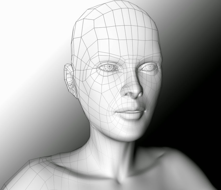
Once you understand how to use these techniques and shortcuts, you'll have access to creating more objects by modelling them yourself, for example, turning a cube into a table, or a plane into a room, or a simple curve into a wine bottle.


In this tutorial, I'll be explain each polygon modelling technique, and show you an example of each technique. I'll also give you the shortcuts for the techniques that have them.

Polygon Modelling Basics

Polygon Modelling techniques are applied to the three different parts of an object in edit mode; Faces, Vertices, and Edges. These can be selected in Edit Mode (tab), and are located at the bottom of the screen (only when in edit mode) as shown below.

From Left: Vertex select, Edge select, Face select

Face: 

This is the surface between three or more Vertices.

Face Select

Vertex: 

These are the points that are located at the end of every Edge.

Vertex Select

Edge: 

These are the lines that connect two Vertices, and surround Faces.

Edge Select

Polygon Modelling Techniques

*Keyboard shortcuts are in brackets

Extrude (E):

This extracts a new edge, face or vertex from one that has already been selected. For example, you can extrude a face from a selected face, an edge from a selected face, and a vertex from a selected vertex.

Extruded Edge

Bevel (Ctrl + B):

Bevel can only be applied to the faces of objects. Its function is to create an additional face below the one that is selected, which in turn, angles the edges between the faces on the object.

Bevel Technique

Inset (i):

This technique can only be used on the faces of objects. Inset allows you to create another face inside the one that you had previously selected.

Inset Technique

Spin:

Spin is used to rotate a face or edge that is selected around an axis, based on where the placement of the 3D Cursor is on the project. There is no keyboard shortcut so just use the spin button and options in the toolbar.

Spin Technique on face

Merge (Alt + M):

This technique merges multiple  vertices, edges, or faces together. It is generally only used on vertices or edges.

Merge Technique

Subdivide:

Subdivide is used to divide the face of an object into separate segments, thus creating more faces upon the one that has been divided. There is no keyboard shortcut so just use the sub-divide button and options in the toolbar.

Subdivided Technique

Knife (K):

The knife technique allows you to manually cut through vertices and faces, creating new vertices, edges and faces.

Knife Technique used to cut surface of face

Loop, cut and slide (Ctrl + R): 

This is a process with three parts, as the name suggests - loop, cut, and slide. The first is to loop a selection around an object, choosing which axis to cut on. The second is cut, which cuts the object on the chosen axis. The final is slide, in which you can slide the cut along the edge or face, before clicking and finishing the cut.


Loop
Cut
Slide

Fill (F):

This allows the user to fill in a gap that may appear in an object in the scene.

Gap that may appear
Gap is filled in with Fill technique

Bisect:

This is used to split objects into separate sections. There is no keyboard shortcut so just use the bisect button and options in the tool bar.

Manual Bisection
Lifted Bisection to show properly

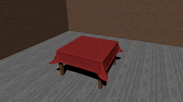
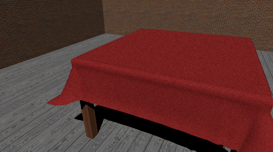
Try some of these techniques yourself. Once you familiarize yourself with them, you can go onto experiment and make a lot of high quality objects and scenes in Blender.

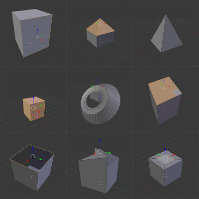
Sample scene created with Polygon Modelling techniques


Wednesday, July 13, 2016

3D Modelling Basics & Terminology3D

3D Modelling Basics
3D Modelling Software Screenshot


This article on 3D modelling is the first of 5 articles on the topic of 3D Graphics and Animation. In this instance, 3D graphics means computer generated three-dimensional graphics. In 3D graphics, elements are visualized by creating three-dimensional models out of them. The final image is rendered from a virtual scene that utilizes several elements which are familiar from real life such as lights, materials and cameras. 3D graphics can be seen in multiple different forms such as an image, an animation or real time visualization inside of a computer game.

The creation of 3D graphics is a complicated process and therefore is, in my opinion, easier to understand when discussed in small pieces, hence the 5 article series. First up it's 3D Modelling which refers to the creation of the 3D model itself.


3D Modelling - The Parts...

A 3D model is a mathematical representation of an object. 3D modelling can be compared to sculpting. Artist builds or moulds a 3D object by taking into account all different sides and angles. 3D models consist of smaller elements (vertex, edge, face, polygon) which can be manipulated individually in whatever software you are using to model your 3D object, such as Blender, Maya or 3D Studio Max.

Vertex:

3d modelling vertex
vertex


Vertex is the smallest building block of a 3D model. Vertex is a point where two or more edges meet and where corners of faces or polygons meet. In a 3D model a vertex is shared between all connecting edges, faces and polygons. Transforming a vertex affects all connected edges, faces and polygons.

Edge:

3d modelling edge
edge

Edge is a line between two vertices. Edges are border lines of faces and polygons. In a 3D model an edge is shared between two adjacent faces or polygons. Transforming an edge affects all connected vertices, faces and polygons.

Face:

3d modelling face
face


Face is a triangle. Face is a surface between three corner vertices and three surrounding edges. Transforming a face affects all connected vertices, edges and polygons.

Polygon:

polygon
polygon

Polygon is an even surface which has four or more corners and is made of two or more faces. A polygon is surrounded by edges and has a vertex in each corner. Animated high quality 3D characters are often made mostly of four-sided polygons. Polygons with 5 or more sides can cause problems in deforming surfaces such as a human face.

3D Modelling - The Techniques...

3D models can be created in many different ways. The choice of modelling technique depends on the requirements and the complexity of the object. The following list describes some of popular 3D modelling techniques:

Standard Primitives and Modifiers:

3d modelling Primitives and Modifiers
Primitives and Modifiers

Many 3D software packages include tools for creating standard objects such as boxes and spheres easily. One of the simplest 3D modelling techniques is to combine these standard objects to create complex 3D models. 3D Studio MAX includes standard objects such as sphere, cube and tube. These standard objects can be modified through their parameters (radius, height etc.) or through special modifiers (stretch, bend etc.). By combining several different standard objects and by modifying them, one can create complex 3D models.

Polygon Modelling:

Stages of Polygon Modelling

Complex objects are often modeled polygon by polygon. 3D software packages include many efficient tools for creating and manipulating polygons.
Subdivision surface means a surface which is created by dividing the original 3D model into smaller polygons. At the same time 3D model's corners become rounder and the surface becomes smoother. Subdivision surfaces is a very popular modelling technique. The advantage of a subdivision surface is the fact that one can create a coarse 3D model which is then automatically subdivided into a smoother surface.


3d modelling
A Polygon Model Before and After Subdivision

Boolean Operations:

The starting point of Boolean operation is two overlapping 3D objects. Boolean operations are prone to error and the resulting geometry might have underlying problems.


3d boolean modelling
Boolean Modelling

Boolean operation has four possible results:

The 4 Possible Outcomes of a Boolean Operation
The 4 Possible Outcomes of a Boolean Operation 
  • Union: Two 3D models are combined and the unnecessary geometry inside of the Models is removed.
  • Intersection: Overlapping a part of the two 3D objects.
  • Subtraction (A-B): Object A is subtracted from object B.
  • Subtraction (B-A): Object B is subtracted from object A.


NURBS:

NURBS stands for Non-Uniform Rational B-spline. In NURBS modelling, lines and surfaces are not manipulated by moving vertices, edges, faces or polygons. Instead NURBS surfaces and lines are manipulated by special control points. The following 2 techniques make use of NURBS.

Solid of Revolution:

A cross section and the object created by a solid of revolution

Solid of revolution is made of one line. The line represents a half cross-section of the object. Solid of revolution is created by revolving the line around a specified axis which then creates the form of the object in 3D.

Lines:

A 3D object and the cage of lines used to create it

3D objects can be created by creating a cage of lines which can be then be converted to a solid 3D surface. This can be a difficult technique to master as it can be hard to visualise the outcome of the lines once they are solidified but once mastered it allows for very quick modelling of objects.

Now that you understand the basics of 3D modelling, why not give it a try, it won't cost you a penny either! We recommend the free software Blender to get you started but there are many other great free 3D modellling softwares. The tutorials linked to below are also a good place to learn the basics of modelling 3D objects. 

Or, if you're not ready for that yet, read the next tutorial in the 3D Modelling and Animation series - 3D Lighting techniques.


Thursday, January 21, 2016

Creating a Room in Blender

Creating a Room in Blender
Final Render of a basic room in blender


In Blender, we use rendering to complete the creation of our 3D scenes and objects. It is used to showcase the scene with all applied textures, materials and lighting, in order to give it the realistic appearance we aim for. We used this process to complete work with the highest standard possible.


In this tutorial, we will be focusing on the actual rendering of the scene. To begin, I will create a room scene, and ensure that the lighting is correctly added, as well as the materials and textures to each object. I will provide a walk-through on how I go about creating this room scene.


Step 1: Making the Tabletop

My scene will mostly be made up of planes, which can be added by pressing shift + A. The plane is located in the ‘Mesh’ dropdown. For this tutorial, I started with a table, and scaled it (S) by 2. Then lift the table on the 'Z' axis, by pressing the 'G' key, then 'Z', then type '2.5'. This will lift the plane higher and give room for the table legs. 

Added Plane
You may want to extrude the tabletop, so as to make it thicker as well. To do this, select the table and enter edit mode (tab). Ensure that Blender is in 'Face Select' (located at the bottom of your screen), and extrude the tabletop (E). You can make it as thick as you want it to be by entering a number after pressing 'E'. My tabletop is '0.1' extruded.


Extruded Tabletop

Step 2: Making the Table Legs

Once we have scaled the plane, go into edit mode (tab) and ensure that the 'Face select' is on (located on the bar at the bottom of the screen). Once you're sure it's on, I would advise using Isometric view by pressing 5, then pres Ctrl+7 to view the bottom of your object, then click subdivide (located on the left in edit mode) three or four times, depending on how wide you want the tables legs to be.


Scaled plane in edit mode

Subdivided plane, with corners selected

Once you have finished subdividing the bottom of your table-top, press shift + right-click each corner face. You can then extrude (E) these faces and in doing so, create your table legs.

Extruded table legs

Step 3: Making the Table Cloth

You can then add a table cloth over the top of the table. In order to do this we must simply add another plane, and scale it up. For this tutorial, I scaled mine by 3. Then grab it (G), and bring it up over the table. You can do this by pulling it up by the blue arrow on screen also.


Cloth plane added
After you have moved the cloth, go into edit mode (tab) and click 'Subdivide' around 5-6 times. This will divide the plane's faces, which will play an important role in giving it the fabric-look we want it to have. Go into the 'Physics' tab on the right hand side of the screen.


Edit Mode Menu
Cloth plane subdivided

Cloth Physics
Add the 'Collision' and 'Cloth' physics to the object. You should then select the table and enable the 'Collision' physics for that as well. These physics allow the cloth to fall onto the table and register the table as something to make contact with in the scene.


Once this is done, select the 'Play Animation' button at the bottom of your screen (or use Alt + A). You should see the table cloth you had previously created drop onto the table and take the appearance of a realistic piece of fabric.


'Play Animation' - Middle-Right play button

You may notice how the cloth may still look slightly unrealistic, as shown below:


Unrealistic Cloth

To fix this, simply select the cloth and select the 'Smooth' button underneath the 'Shading' dropdown on the left hand side of the screen.

Shading Settings
The fabric will then appear as shown below, which is much smoother and realistic:


Realistic, 'Smooth' cloth

Step 4: Making the Floor

Once the physics have been applied to the table cloth and table, you can move onto making the actual room. This requires only three planes, each scaled up to represent the walls and the floor.

Added Floor
Add your first plane. This will be the floor of the room. In my own scene, I scaled it by 10. It's far easier working with even numbers when creating room scenes. 


Scaled Floor

Step 5: Making and Moving the Walls

Once you've scaled the floor, you need to add two more planes for the walls. Again, add a plane from the 'Mesh' menu. Rotate it on the 'X' axis ('R', 'X') by 90 degrees. Then proceed to move the plane along the 'Y' axis by 10. It should appear as follows.

First wall moved
The next step is to scale the wall to fit along the floor, and make it taller. To scale it to fit the floor only, it's important that you only scale it on the 'X' axis. This will increase the length of it only. Do this by pressing the scale key (S), then 'X', and finally scale it by ten. Then proceed to do the same again, except on the 'Y' axis and by 5. You should then grab the wall, and move it up on the 'Z' axis until the bottom of the wall is in line with the floor (follow this sequence for accuracy; 'G', 'Z', 5)

It should appear as follows:

First wall scaled
After you've finished this, you need to repeat the process of creating a wall, only this time, things should be done the other way around. Add your second plane, and rotate it on the 'Y' axis this time. Then move it on the 'X' axis by 10. 
It should appear as follows:

Second wall moved

Then proceed to scale the wall on the 'Y' axis, by 10. Again, you will see that this will make the plane as long as the floor. Make this wall the same height as the other by scaling it on the 'Z' axis, just as you had done before, and move it up on the 'Z' axis by 5.

It should look like this:

All walls added

Step 6: Adding Materials and Textures

Once you've finished the room, you will probably want to add materials and textures. To do this, you must select each object and add a material to each. This can be done in the materials tab on the right hand side of the screen, as shown below:


Materials tab highlighted
Texture Tab highlighted


In this tab, select the 'New' button. This will give the object a material. Materials have to be added to an object in order to use textures to make the object appear more realistic.


After the material has been added, proceed to the Textures tab, which is directly to the right of the materials tab. Then select the 'New' button, and use the 'Open' selection under the 'Image' dropdown to open whichever texture you wish to use from your computer. Do this for each object.

If you were to select the 'Rendered' view now, you would see the room with all it's textures and materials added to each object, however, you may notice that each object may an unrealistic shine to it - depending on where your lamp placement is. If you want to get rid of this and produce a more realistic scene, simply select an object, go onto your 'Materials' tab, and turn the 'Intensity' under 'Specular' down to zero. This reduces the shine of the objects in your scene. You will need to do this for each object.

Specular in Materials Tab

Step 7: Lighting

Before you complete your final render, you may want to change or alter the lighting in the scene. For this tutorial, I used a 'Sun' light, which is a light that does not originate from a certain point, but simply from the sky in Blender. It acts as general sunlight, and can create shadows, which is the reason I did not create a roof on the scene.


Sun Light


You may want to experiment with your own lighting, by selecting the lamp and trying out the different options.

Step 8: Final Render

Finally, we can render our scene. To render the scene, press 'F12' on your keyboard. This will give you a rendered view through the camera on your scene. If the render is not centering at the point in which you want it to, you can move your camera around on the 'X', 'Y' and 'Z' axis'.


Camera selected and moved


Once you are satisfied with your camera placement, you will end up with a final render that you feel is the best, probably something like the following:


Final Render


Final Render 2


Final Render 3


close
Banner iklan disini