Showing posts with label 3d software. Show all posts

Tuesday, February 13, 2018

Best Free 3D Modelling Softwares

best free 3d modelling software
The best free 3d modelling softwares available

There are a large selection of quality 3D software packages on the market but unfortunately many of the top applications available cost hundreds or even thousands of dollars.  However, there are also number of free 3D softwares out there for hobbyists, independent filmmakers and animators, freelance designers, architects and game developers who don't have the budget for expensive software.

There are dozens of other free 3D tools available beyond what is mentioned here. However, these are the strongest of the bunch,covering a range of 3D modelling areas such as architecture, engineering, character modelling, animation and more. So here is our top 10 free 3D modelling softwares...


Open SCAD

Rating: 2 star free 3D modeling software

A free 3D-modeling software for Windows, Mac OS, and Linux, Open SCAD focuses more on the CAD aspects of modeling an object rather than the artistic aspect. Unlike many others listed on this page, Open SCAD is not an interactive modeler but a 3D-compiler modeler that reads in the details of the objects to render their 3D models on the screen. This is definitely a novel and interesting approach which may suit those who find it difficult to visualize objects in 3D.

It describes itself as "the programmers Solid 3D CAD modeller". This is great if your a programmer but if you aren't then best stay clear of this option.

Visit Website


Tinkercad

Rating: 3 star free 3D modeling software

Tinkercad can be used as a 3D design platform, or as a 3D printing service. Itis a free web-based app which runs on Windows, Mac and Linux operating systems. Tinkercad’s 3D design tools are accessible to beginners and experienced designers alike. Shapes that you place on a design field are stretched, contorted and combined to make your 3D model. You can group shapes to together to make more detailed designs, or import 2D or 3D vector shapes that can be extruded into 3D models.

If you’re new to 3D design, Tinkercad provides a number of tools and tutorials that enable you to explore and learn about the process. Tinkercad offers step-by-step lessons on the design process to help newcomers get acclimated. It also allows you to browse its library of more than 4 million pre-created designs to get ideas and learn tricks from other designers in the community. The platform also provides 3D printing services, so your models can be printed and shipped straight to your door.

Visit Website


Pixologic Sculptris

Rating: 3 star free 3D modeling software

Sculptris provides an excellent gateway into the exciting world of 3D. Its features are easy to learn, navigate and use, even for someone with no experience in digital art or modeling yet robust enough for creating base models that can then be refined in other applications, such as ZBrush. It will dynamically divide the model, better handling your computer’s resources.

This is certainly an easy to use software but it is geared specifically toward one type of 3d modelling (sculpting) and therefore is restrictive for anyone who needs a software with multiple modelling approaches, animation tools or the accuracy of geometric modelling. In summary it's really only useful for mocking up character models or creating static models for 3D printing.

Visit Website


Wings 3D

Rating: 3 star free 3D modeling software

Wings 3D is an advanced sub-division modeler which offers a wide range of modeling tools and a customizable interface, along with a built-in autoUV mapping tool, vertex colors, materials, and Lighting as well as export facility for common 3D formats  like .obj.

However, despite more awesome features like support for virtual mirroring for symmetric modeling, Wings 3D provides no support for animation for its users. It is also solely a mesh/polygon modelling software so there are no options for sculpting like in Sculptris (above).

Visit Website


PTC Creo

Rating: 3 star free 3D modeling software

Ok, so first off this one is not totally free like the others but it is free for students and teachers while offering the usual 30 day free trial for everyone else. Creo is also a very use friendly software. It's good for handling assembly features and that's why its used in most of the engineering companies in the field of design, assembly and manufacturing.

Creo is a comprehensive system for mechanical engineers and product designers who create using the direct modeling approach of 3D CAD. Direct modeling allows the creation of designs by existing designs or fresh ideas. Hence, the changes to the geometry of an object can be made quickly and easily.

Not for architects, game developers, animators or hobby modelers.

Visit Website


FreeCAD

Rating: 4 star free 3D modeling software

FreeCAD is a parametric 3D modeler made primarily to design real-life objects of any size. Targeted at architects, engineers and product designers. The program is a multi-platform (Windows, Mac OS, and Linux) tool, and reads and writes various open file formats.

FreeCAD is easy to use with no previous CAD experience required and the online community will help you get the hang of it quickly if you do need help. If you use commercial CAD or BIM modeling software at work, you will find similar tools and workflow among the many workbenches.

Almost all of FreeCAD's functionality is accessible to Python s if you know Python you can extend FreeCAD's functionality, automatize it with scripts, build your own modules or even embed into your own application.

Visit Website

Vectary

Rating: 4 star free 3D modeling software

Vectary is an online 3D modeling tool with which you can create, share and customize 3D designs. It is a combination of standard mesh modeling, subdivision modeling and parametric plugins. It was built from scratch to make 3D modeling easy-to-use for beginners, and is also useful to pros. You can export your models to standard 3D files, print them or continue your work in a compatible software. You can also choose from a growing list of parametric plugins that do the work for you.

The user interface is beautifully simple with integrated tutorials for beginners which speed up the learning process. Being an online editor is both an advantage and disadvantage as you can acces files from your account anywhere while also meaning you can't use it if you don't have internet access.

There is currently no animation functionality but it seems to be a fast evolving software so we may see some animation features added in future.

Visit Website


Daz Studio

Rating: 4 star free 3D modeling software

Daz 3D is a versatile and feature-rich suite of 3D figure posing, animation, and rendering applications designed for 3D animators, designers, and illustrators. It is comprised of graphic design software solutions, platforms, and add-ons that enable them to create rigged 3D human models and stunning digital illustrations, animations, and environments. Additionally, the suite provides a user-friendly modeling software that helps in modeling, posing, animating, morphing, and rendering 3D content. It comes with a 3D creation software tool that is equipped with GPU-accelerated real-time rendering capabilities.

The software's animation and rendering tool-set is fairly robust, and in the right hands users can create impressive shots. However, without a full range of modeling, surfacing, or sculpting tools built in, your content can become limited unless you're willing to buy 3D assets in the Daz marketplace or create them yourself with a 3rd party modeling package.

Visit Website


SketchUp Free

Rating: 4 star free 3D modeling software

SketchUp Free is great for planning out a 3D space quickly, ideal for student or freelance architects.Maneuvering around this program is pretty easy thanks to the highly customizable palettes. The program gives you the freedom to add, remove, or rearrange the palettes to appear the way you want. Its large icon replaces the feature list of most CAD software thereby allowing the user to easily find the commands. 

Most the features provided by Sketchup are fundamentally focused on 3D designing. However, the program has features and tools that support 2D designing. This makes it an ideal application for beginners looking to plan, visualize, and communicate future construction projects. The SketchUp warehouse is also an amazing extension that allows you to use pre-built assets from other users, speeding up the design process even more.

Visit Website


Blender - Editor's Choice

Rating: 5 star free 3D modeling software

Blender is easily the most versatile and entry on this list, and in many regards, it compares favorably to premium digital content creation tools like Cinema 4D, Maya, and 3ds Max. It is a free and open source 3D creation suite which supports the entirety of the 3D pipeline, offering a complete range of modeling, surfacing, sculpting, painting, animation, and rendering tools.

The software is good enough to have produced numerous impressive short films and is in use by several professional studios. The software was given a thorough overhaul about a year ago and emerged with a fresh interface and a feature set that aims for parity with the best. Blender has steadily carved out a niche in motion graphics and visualization, similar to where Cinema 4D excels.


Thursday, October 6, 2016

Read Creating A Speed Pick Up in UE4 Now

This the pick up that we will be making.
Welcome to this tutorial, today we will be creating a pick up that, rotates, bops up and down, and also increases your characters speed.

Step 1: Creating a New Blueprint

The first thing that we need to do is create a new blueprint, to do this in the content browser, open the blueprints folder then right click on an empty space and select blue print from the pop up menu.

This picture shows where I have a pick up.

This tutorial is being made in UE4s latest version.
When you select Blueprint, this window will pop up. from here we want to select actor.

From this we select actor.

Step 2: Creating the Collision

Now that we have our actor created double click on the thumbnail, this will open the editor for that blueprint.

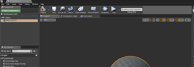
This is the blue print editor for the blueprint we created.

In here we need to add a collision, so in the top right, it will say '+Add Component'. Click this and select sphere collision, if you are using an older version of UE4 you can select a sphere. I named mine collision once brought in.

This is the sphere collision.

Now that we have this created, we need to add a static mesh, to do this we need to be able to see both the blue print editor and the props folder in the starter content. Im going to select the material sphere and drag it into the blueprint editor and drop it in the grey space under the add component section.

This is the material sphere in the blueprint editor.

As we can see from the above picture the sphere has swallowed our collision. So im going to use the scale widget to scale my material sphere down. To do this, select the ball, press the space key twice, the widget you are looking for looks like this,

Scale Widget

What Im going to do to scale the ball so it doesnt become an egg, select one of the arrows, click and drag one step, once you use the widget you will see what I mean. Start with the green arrow and work around, scaling down one at a time until the collision resurfaces over the sphere.

The scaled down version.
We need to change the presets of the ball to Overlap all. Scroll down the menu on the left handside, for the collision and the mesh. You will see the Blockall Dynamic, change this to overlap all.

I have the options changed on the left of the screen.

From the picture below select the event graph option so that we can start our blueprints coding.

Event graph is the third tab above the sphere.


Step 3: Blueprints for rotation

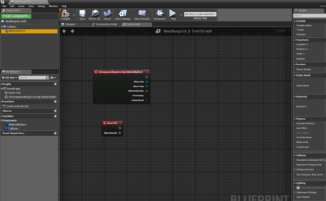
When your in the event graph this is how it should look.

Older versions will have different organised details panels.

Ive just deleted all of the coding to start fresh.

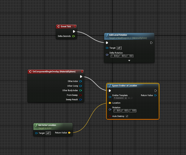
The next thing that we do is right click on the grid, and search for event tick once this has been added, select the material sphere in the top right hand panel, then right click, open add event section, then select the collision drop down option, and from there select begin overlap.

The beginnings of the coding.
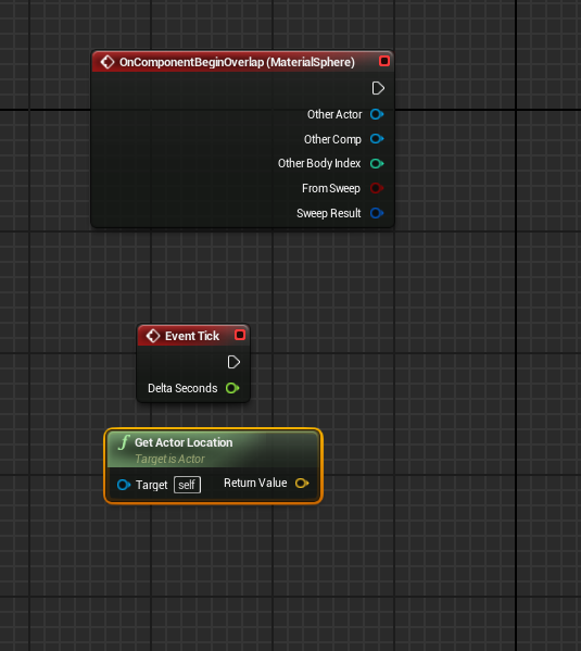
Right click on the grid again, this time type 'actor location' into the search bar, select the green option that says, 'get actor location'.

This is the added get actor location code.

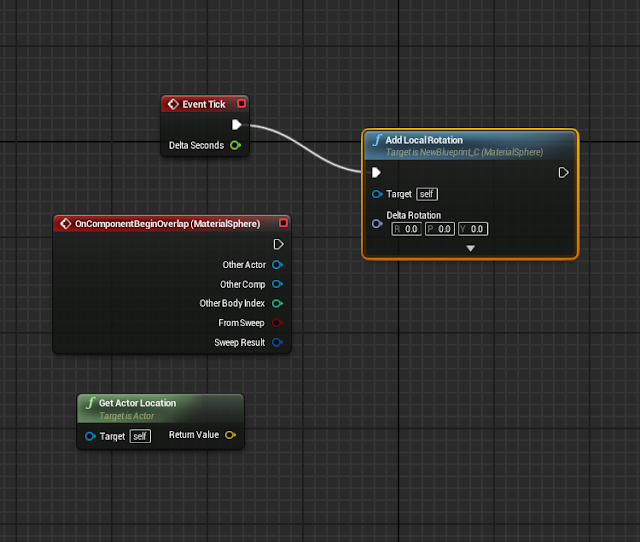
We are going to start making the pick up rotate, the first thing I did was move the event tick above the begin overlap. From the white arrow, drag out and when you release you have the option to search, look for 'local rotation'. The newer version will give you the option to apply the rotation to either the material sphere or the collision, we want to select the material sphere version. In the older versions of the programme you don't need to worry about what to select.

Once we have selected the node to add it is then connected.

The next thing that we will add is an emitter, for this I dragged from the white arrow on the begin overlap node, in the search bar I typed 'emitter', from the options you want to select spawn emitter at location.

In the newly added node, under the emitter template drop down, select the explosion option.

Then we connect the green node into the location.

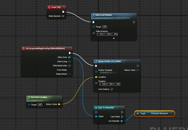
The next pieces of code we are going to add are brought out from the begin overlap node, in this node select the blue other actor circle, drag this out and type 'cast character' select my character from the options. Once this has been added hit save, just to be safe.

Then from the cast character node drag out the blue circle and search for character movement, you need to scroll down to the bottom of the results in order to find the 'Variables' section, there will only be one option here and that is the one that we want.

We are nearing the completion of our coding.

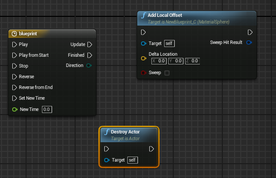
This time we will add three pieces of coding that will complete the coding that we need to gather in order to create the floating pick up, for now will we just grab it all and put it into the grid.. 
First thing to do is right click, from the pop up scroll down to the bottom and select the timeline option, name this blueprint.

The second piece is right click, followed by a search for 'local offset' add this beside the timeline.
The last piece we are going to add in this section is a destroy actor node, right click search destroy actor and add this into the grid.

We will connect this in the next step.

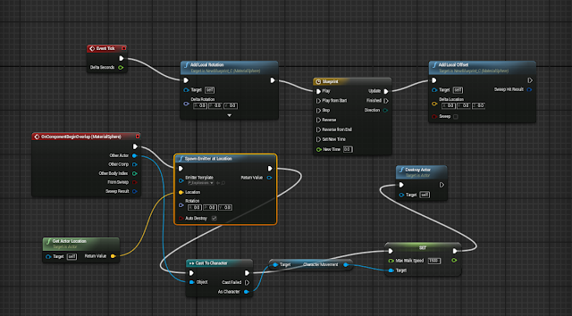
The last piece of coding that needs to be added is a 'set max walk speed' node. Drag out from the character movement reference, right click and search walk speed, you may need to turn off the context sensitive option in order to find it, select the node that says 'set max walk speed'. Once you have added this piece of code, change the value to 1500, then connect all of the coding up as you see below.

This is the coding complete for now. The walk speed value is now 1500.


Step 4: Creating the up/ down motion on our pick up


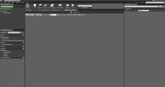
To add this select the timeline node in the blueprint and double click, this is the window that you will see, when this opens select the V option to add a vector track.

The Vector track is how we will create the bop effect.

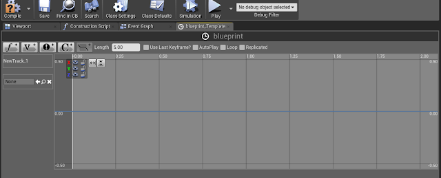
This image below shows how our window will look once we have applied the vector track.

Added Vector Track.

Step 5: Adding Key Frames to a Vector Track

We are going to be adding our key frames on the Z axis, because we want our ball to go up and down in the air.

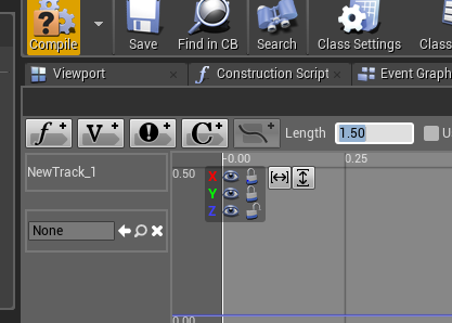
To do this we need to click the lock symbol beside the green, and red boxes in the top corner of our vector track, this will only leave the Z axis available to work on.

The x, y axis is locked and have the length set 1.50.
To add a key frame we go to the start of the animation on the blue line, where it says 0.00 hold down the shift key and left click in order to add a keyframe.

This will bring up some options seen below.

Set both values to 0.00.
Next we make sure to have the Z axis only unlocked, and we do another key frame, this time at the 0.50 point. the values this time are .5 and .5.

Second key frame added.

The next key frame will be added at the 1.00 mark. The values this time will be 1.00 and then -0.05.

Third key frame creating motion.

The final key frame will be added at the 1.50 mark, the values this time are 1.50 followed by 0.00. We are also going to need to tick the loop option. Dont forget to compile and save.

Here we also change the length to 1.50.
Now we can go back to the graph, we now have an extra option on our timeline node and this needs to be connected.

Connect the yellow into the yellow and compile/ save.

Now that everything is connected and complied we can play and try it out. The orb will bounce up and down whilst rotating and will allow our character to increase their speed by hitting it.


Step 6: Adding a material to the pick up

To add a material to the sphere we open the sphere in the blueprints folder. 

The sphere is selected in the blueprints editor.
From here if you look at the above picture you can see, on the left hand side of the screen, static mesh, double click on this thumbnail image and it will open up a new window that looks like this.

This is the editor for the sphere.
All we need to do now is drag a material from the content browser onto the section on the right hand side that has the ball in it, this will apply the material and then you can hit save.

This is the texture I chose for my pick up.
This concludes the tutorial. When you hit play you will have a fancy functional pick up.

Read How to make a sword in Blender Now


finished result 

In this tutorial you learn the necessary skills on how to make a sword. In this tutorial we will be making a Japanese Katana.


Part 1 The Blade


Change to cycles render

Cycles Render


Delete cube, press 1 and then 5 for orthographic view, shift A to add plane, R to rotate on the X axis by pressing X then 90.

plane 


Tab for edit mode S scale on the X axis

plane scaled 


Press shift and tab for the snap during transform button or hit the magnet button, select the top vertex
Snap during transform 


vertex selected


E to extrude up to 16 boxes, turn on proportional editing,

extruded plane


Once proportional editing is on G to grab on the X axis, scroll mouse button

Proportional editing

Change to sharp

sharp

Move too two boxes to the right
sharp tool in use

Click the right vertex then the second, press W to merge, at first,

merge

at first

merged point 


Turn proportional editing and snap during transform off, select the outside of the blade by pressing B and dragging it along the left side or by selecting each vertex individual by hitting shift and right clickE to extrude on the X axis a small bit.


extruded


Merge the top vertex, move the bottom one slightly to the right

merged


Press A to select everything, change view by 3 on the keypad, E to extrude.
extruded

Merge the two points together

merged points 

Select the next vertex underneath the top point and its opposite one press W , merge, at centre do this to the rest.
at center

To fix the lighting and shade go to mesh, normals, recalculate outside or inside this will prevent the blade from being dark at certain angles.

Normals 

Tab and smooth. the smooth button is to the left it will show if your out of edit mode. add a modifier, subdivision surface, change render to 1.The blade will look off, go into edit mode by pressing Tab, select the these 4 vertex

subdivision

4 points selected


To fix the problem that will happen go to mesh, edges, edge crease. once clicked drag your mouse across the screen to the right side. this fill the empty space, repeat this for the bottom of the blade.

edge crease

using edge crease


edge crease used at the top of the sword


edge crease used at the bottom of the sword

To add a flare onto it create a loop cut ctrl R lenght wise twice 

creating a flare in the sword

Press E to extrude and right click straight away so it sits on top, S scale on the Y axis pull it in to your desired depth. Then add edge crease to make the depth stand out.

adding depth 


Part 2 The Hilt 

Select all of the vertexes by pressing  Band dragging it across or by selecting each one individual by shift and right click.
bottom all selected

Mesh, snap cursor to selected that will center the 3d cursor at the bottom of the blade, shift A add a circle, tab into edit mode, select these vertices
six vertices selected

S scale them inwards like so

scale inwards

go into front view 1 select the circle E extrude on the Z axis


extrude

 Create a face by hitting F

add face


E to extrude right click straight away scale a small bit extrude on the Z axis downward to create a small lip. Repeat this step for the bottom

creating small lip


Click on the hilt, click on smooth this will create an issue to fix this, add a modifier, edge split this will fix it.

smooth

edge split
Select the face underneath the the hilt, then place the cursor in the centre by going to mesh, snap, cursor to centred. add a circle by shift A, add circle, S for scale to whatever size you want your handle to be.

circle 


scale

scale on x,z,y axis 


 E extrude a small bit downwards, press enter  extrude right click straight away scale a notch inwards to create a small lip then extrude to your desired length

extrude

extrude

Extrude again, scale inwards and create a face by hitting

add face


Select the top vertex,

top selected

 shift D to duplicate, right click to place then right on top, hit P to make it a brand new section.

duplicate


 Drag it down, extrude around this size, create three loop cuts

creating loop cuts


Use the knife tool, hit Z so it will cut through the mesh, create a diamond shape, select all the faces and press X delete faces.

Knife tool


selected faces

Add an Array modifier 

Array modifier 

Use this to move and duplicate the design onto the hilt 

Array modifier 


Array modifier used

To add a material and a texture check out the tutorial on how to add a texture in Blender at

Add lighting around the scene by hitting shift A, lamp choose a type a light that suits you.
you can check the tutorial about adding light in Blender 

light placed in scene

rendered view


close
Banner iklan disini