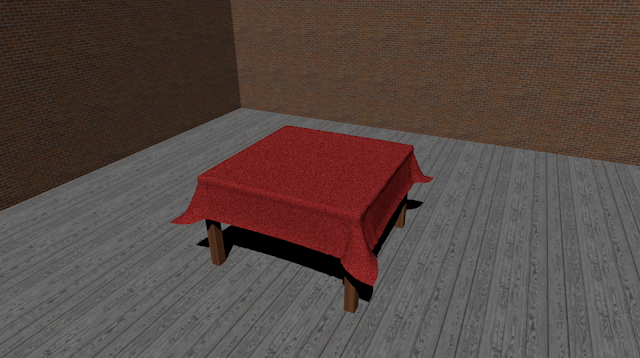
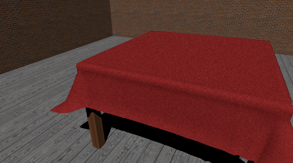
Showing posts with label 3d materials. Show all posts

Thursday, October 6, 2016

Read How to add a texture in Blender Now

rendered result

In this tutorial you will learn how to add a texture in Blender using Cycles render.

Step 1

Using whatever you have made or imported change the default screen layout to compositing for a detailed result.

changing layout to compositing 

Step 2 

Change blender render to cycles render at the top of the screen.
Blender Render

Cycles Render

Step 3

Right click in the plane, click on the material button on the top right corner of the screen, click new.

adding a material

Step 4

If a material is already in place use the subtract button then press new.

subtracting the existing material 

Step 5

Click on the dot right of the white colour.


Step 6


Select image texture, press open and navigate to the image you want to use, once selected open the image/texture.
opening a image texture

Step 7

To map the image on the plane go to edit mode by pressing Tab or changing it from the bar menu.

changing to edit mode

Step 8

Press A to deselect then A again to select everything. go to mesh, UV unwrap, unwrap.

unwrapping the cube

Step 9

On the left side the plane will be unwrapped. Next load the image.

applying the image onto the cube

Step 10 

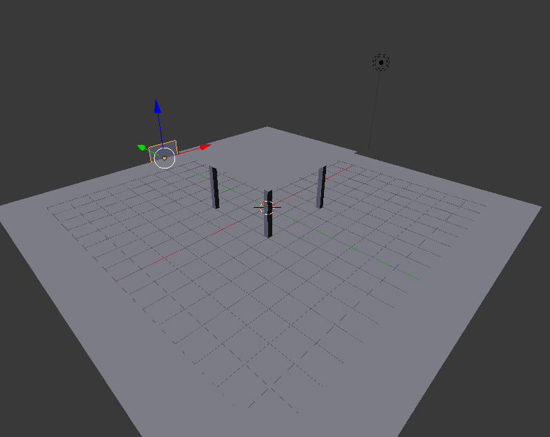
Switch back to object mode, switch back to the default layout, go to render to see the result.

changing to rendered view


Rendered result 


Saturday, February 13, 2016

UE4 Pickups

This tutorial is the fifth in the 10 part series on how to create a first person shooter game using Unreal Engine 4. We recommend you read the previous articles first to get the maximum benefit from this tutorial.

Step 1: Creating A New Blueprint 

UE4 Pickups

The first thing we need to do is create a new blueprint, to do this in the content browser, open the blueprints folder then right click on empty space and select blueprint from the pop up menu.


When you want to select blueprint, this window will pop up. We want to select actor.

Step 2: Creating The Collision


Now that we have our actor created double click on the thumbnail, this will open the editor for that blueprint. We need to add a collision, so in the top right, it will say add component. Click this and select sphere collision.

If you are using a older version of Unreal Engine 4 you can select a sphere.
Then we need to add a static mesh, to do this we need to see both the blue print editor and the props folder in the starter content select the material sphere and drag it into the blueprint editor and drop it in the grey space under the add component section.
Scale widget 
Use the scale widget to scale the sphere down. To do this, select the ball, press the space key twice and locate the widget you are looking for.


We need to add a static mesh, to do this we need to be able to see both the blueprint editor and the props folder

As we see from the above picture the sphere has swallowed the collision

Step 3: Blueprints for rotation


Event graph shows up


The next thing we do is right click on the grid and search for event tick once this has been added, select the material sphere in the top left hand panel, then right click, open add event section, then select the collision drop down option and from there select begin overlap.


Right click on the grid again, this time type actor location into the search bar, select the green option that says get actor location. The next thing that we will add is an emitter, for this drag from the white arrow on the begin overlap node, in the search bar type emitter.


From the options you want to select spawn emitter at location. In the newly added node, under the emitter template drop down, select the explosion option.


The next pieces of code we are going to add are brought out from the begin overlap node. In this node select the blue other actor circle, drag this out and type cast character select my character from the options menu. Once this has been added hit save.


Then from the cast character node drag out the blue circle and search for character movement, you need to scroll down to the bottom of the results in order to find the variables section.

There will only be one option here and that is the one that we need. This time we will add three pieces of coding that will complete the coding that we need to gather in order to create to the floating pickup, just grab it and put it into the grid.

Next thing is to right click from the pop up scroll down to the bottom and select the timeline option, name this blueprint. The next piece is right click followed by a search for local offset add this beside the timeline. This piece is we are going to add in this section is a destroy actor node, right click search destroy and add to the grid.


This time we are going to add three pieces of coding that will complete the coding process. We need to gather in order to create the floating pick up. Now we will just grab it all and put it into the grid. First thing to do is right click, from the pop up scroll down to the bottom and select the timeline option, name this blueprint


The second piece is right click followed by a search for local offset add this beside the timeline. The last piece we are going to add in this section is a destroy actor node, right click search destroy actor and add it into the grid.

The last piece of coding that needs to be added is a set max walk speed node. Drag out from the character movement reference, right click and search walk speed, you may need to turn off the context sensitive option in order to find it. Select the node that says set max walk speed. Once you have added this piece of code, change the value to 1500, then connect all of the coding up.


Step 4: Creating The Hover Effect

Vector track
To add this select the timeline node in the blueprint and double click, this is the window that you will see, when this opens select the V option to add a vector track.

Now we are going to be adding our key frames on the z axis, because we want our bell to go up and down in the air. To do this we need to click the lock symbol beside the green, and red boxes in the top corner of our vector track, this will only leave the z axis available to work on.

Adding key frame to vector track 
Adding more key frames to vector track 
To add a key frame we go to the start of the animation on the blue line, where it says 0.00 hold down the shift key and left click in order to add a key frame.

Next we make sure to have the z axis only unlocked, and we do another key frame, this time at the 0.50 point, the values this time are .5 and 5.The next key frame will be added at the 1.00 mark. The values this time will be 1.00 and then -0.05. The final key frame will be added at the 1.50 mark. The values this time are 1.50 followed by 0.00. we are also going to need to tick loop option.

Now we can go back to the graph, we now have an extra option on our timeline node and this needs to be connected. Now that everything is connected and compiled.

Step 5: Adding A Material To The Pickup

To add a material to the sphere open the sphere in the blueprints folder.


From here if you look at the above picture you can see, on the left side of the screen, static mesh, double click on the thumbnail and it will open a new window.


Now we drag a material from the content browser into the section on the right side that the ball is in. The material will work once you save it,


As you can see this are the 3 pick ups we have made in our finished game the heart is for health, the lighting bolt is for a speed up to get away and the boxes are ammo creates. 

Next Up

Now it is time to add detail to our FPS game by adding custom static meshes such as trees, grass, rocks, crates, etc.


Thursday, January 21, 2016

Creating a Room in Blender

Creating a Room in Blender
Final Render of a basic room in blender


In Blender, we use rendering to complete the creation of our 3D scenes and objects. It is used to showcase the scene with all applied textures, materials and lighting, in order to give it the realistic appearance we aim for. We used this process to complete work with the highest standard possible.


In this tutorial, we will be focusing on the actual rendering of the scene. To begin, I will create a room scene, and ensure that the lighting is correctly added, as well as the materials and textures to each object. I will provide a walk-through on how I go about creating this room scene.


Step 1: Making the Tabletop

My scene will mostly be made up of planes, which can be added by pressing shift + A. The plane is located in the ‘Mesh’ dropdown. For this tutorial, I started with a table, and scaled it (S) by 2. Then lift the table on the 'Z' axis, by pressing the 'G' key, then 'Z', then type '2.5'. This will lift the plane higher and give room for the table legs. 

Added Plane
You may want to extrude the tabletop, so as to make it thicker as well. To do this, select the table and enter edit mode (tab). Ensure that Blender is in 'Face Select' (located at the bottom of your screen), and extrude the tabletop (E). You can make it as thick as you want it to be by entering a number after pressing 'E'. My tabletop is '0.1' extruded.


Extruded Tabletop

Step 2: Making the Table Legs

Once we have scaled the plane, go into edit mode (tab) and ensure that the 'Face select' is on (located on the bar at the bottom of the screen). Once you're sure it's on, I would advise using Isometric view by pressing 5, then pres Ctrl+7 to view the bottom of your object, then click subdivide (located on the left in edit mode) three or four times, depending on how wide you want the tables legs to be.


Scaled plane in edit mode

Subdivided plane, with corners selected

Once you have finished subdividing the bottom of your table-top, press shift + right-click each corner face. You can then extrude (E) these faces and in doing so, create your table legs.

Extruded table legs

Step 3: Making the Table Cloth

You can then add a table cloth over the top of the table. In order to do this we must simply add another plane, and scale it up. For this tutorial, I scaled mine by 3. Then grab it (G), and bring it up over the table. You can do this by pulling it up by the blue arrow on screen also.


Cloth plane added
After you have moved the cloth, go into edit mode (tab) and click 'Subdivide' around 5-6 times. This will divide the plane's faces, which will play an important role in giving it the fabric-look we want it to have. Go into the 'Physics' tab on the right hand side of the screen.


Edit Mode Menu
Cloth plane subdivided

Cloth Physics
Add the 'Collision' and 'Cloth' physics to the object. You should then select the table and enable the 'Collision' physics for that as well. These physics allow the cloth to fall onto the table and register the table as something to make contact with in the scene.


Once this is done, select the 'Play Animation' button at the bottom of your screen (or use Alt + A). You should see the table cloth you had previously created drop onto the table and take the appearance of a realistic piece of fabric.


'Play Animation' - Middle-Right play button

You may notice how the cloth may still look slightly unrealistic, as shown below:


Unrealistic Cloth

To fix this, simply select the cloth and select the 'Smooth' button underneath the 'Shading' dropdown on the left hand side of the screen.

Shading Settings
The fabric will then appear as shown below, which is much smoother and realistic:


Realistic, 'Smooth' cloth

Step 4: Making the Floor

Once the physics have been applied to the table cloth and table, you can move onto making the actual room. This requires only three planes, each scaled up to represent the walls and the floor.

Added Floor
Add your first plane. This will be the floor of the room. In my own scene, I scaled it by 10. It's far easier working with even numbers when creating room scenes. 


Scaled Floor

Step 5: Making and Moving the Walls

Once you've scaled the floor, you need to add two more planes for the walls. Again, add a plane from the 'Mesh' menu. Rotate it on the 'X' axis ('R', 'X') by 90 degrees. Then proceed to move the plane along the 'Y' axis by 10. It should appear as follows.

First wall moved
The next step is to scale the wall to fit along the floor, and make it taller. To scale it to fit the floor only, it's important that you only scale it on the 'X' axis. This will increase the length of it only. Do this by pressing the scale key (S), then 'X', and finally scale it by ten. Then proceed to do the same again, except on the 'Y' axis and by 5. You should then grab the wall, and move it up on the 'Z' axis until the bottom of the wall is in line with the floor (follow this sequence for accuracy; 'G', 'Z', 5)

It should appear as follows:

First wall scaled
After you've finished this, you need to repeat the process of creating a wall, only this time, things should be done the other way around. Add your second plane, and rotate it on the 'Y' axis this time. Then move it on the 'X' axis by 10. 
It should appear as follows:

Second wall moved

Then proceed to scale the wall on the 'Y' axis, by 10. Again, you will see that this will make the plane as long as the floor. Make this wall the same height as the other by scaling it on the 'Z' axis, just as you had done before, and move it up on the 'Z' axis by 5.

It should look like this:

All walls added

Step 6: Adding Materials and Textures

Once you've finished the room, you will probably want to add materials and textures. To do this, you must select each object and add a material to each. This can be done in the materials tab on the right hand side of the screen, as shown below:


Materials tab highlighted
Texture Tab highlighted


In this tab, select the 'New' button. This will give the object a material. Materials have to be added to an object in order to use textures to make the object appear more realistic.


After the material has been added, proceed to the Textures tab, which is directly to the right of the materials tab. Then select the 'New' button, and use the 'Open' selection under the 'Image' dropdown to open whichever texture you wish to use from your computer. Do this for each object.

If you were to select the 'Rendered' view now, you would see the room with all it's textures and materials added to each object, however, you may notice that each object may an unrealistic shine to it - depending on where your lamp placement is. If you want to get rid of this and produce a more realistic scene, simply select an object, go onto your 'Materials' tab, and turn the 'Intensity' under 'Specular' down to zero. This reduces the shine of the objects in your scene. You will need to do this for each object.

Specular in Materials Tab

Step 7: Lighting

Before you complete your final render, you may want to change or alter the lighting in the scene. For this tutorial, I used a 'Sun' light, which is a light that does not originate from a certain point, but simply from the sky in Blender. It acts as general sunlight, and can create shadows, which is the reason I did not create a roof on the scene.


Sun Light


You may want to experiment with your own lighting, by selecting the lamp and trying out the different options.

Step 8: Final Render

Finally, we can render our scene. To render the scene, press 'F12' on your keyboard. This will give you a rendered view through the camera on your scene. If the render is not centering at the point in which you want it to, you can move your camera around on the 'X', 'Y' and 'Z' axis'.


Camera selected and moved


Once you are satisfied with your camera placement, you will end up with a final render that you feel is the best, probably something like the following:


Final Render


Final Render 2


Final Render 3


close
Banner iklan disini