Showing posts with label polygon. Show all posts

Thursday, August 11, 2016

Polygon Modelling Techniques

Polygon Modelling Techniques

Polygon Modelling is a technique used to model objects in Blender, or other 3D modelling softwares, in a series of different ways ( Check here to find a free 3D Modelling Software to suit you).

It can be used in a lot of different ways, and is used in a lot of general modelling. Each of these techniques can only be used in edit mode (tab) in Blender.

Once you understand how to use these techniques and shortcuts, you'll have access to creating more objects by modelling them yourself, for example, turning a cube into a table, or a plane into a room, or a simple curve into a wine bottle.


In this tutorial, I'll be explain each polygon modelling technique, and show you an example of each technique. I'll also give you the shortcuts for the techniques that have them.

Polygon Modelling Basics

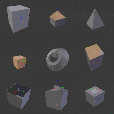
Polygon Modelling techniques are applied to the three different parts of an object in edit mode; Faces, Vertices, and Edges. These can be selected in Edit Mode (tab), and are located at the bottom of the screen (only when in edit mode) as shown below.

From Left: Vertex select, Edge select, Face select

Face: 

This is the surface between three or more Vertices.
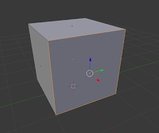
Face Select

Vertex: 

These are the points that are located at the end of every Edge.
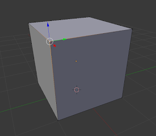
Vertex Select

Edge: 

These are the lines that connect two Vertices, and surround Faces.
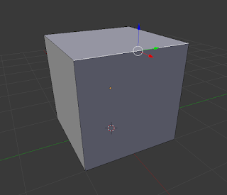
Edge Select

Polygon Modelling Techniques

*Keyboard shortcuts are in brackets

Extrude (E):

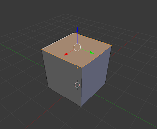
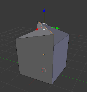
This extracts a new edge, face or vertex from one that has already been selected. For example, you can extrude a face from a selected face, an edge from a selected face, and a vertex from a selected vertex.
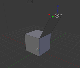
Extruded Edge

Bevel (Ctrl + B):

Bevel can only be applied to the faces of objects. Its function is to create an additional face below the one that is selected, which in turn, angles the edges between the faces on the object.
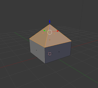
Bevel Technique

Inset (i):

This technique can only be used on the faces of objects. Inset allows you to create another face inside the one that you had previously selected.
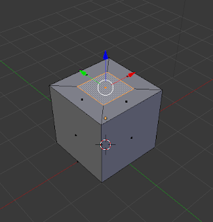
Inset Technique

Spin:

Spin is used to rotate a face or edge that is selected around an axis, based on where the placement of the 3D Cursor is on the project. There is no keyboard shortcut so just use the spin button and options in the toolbar.
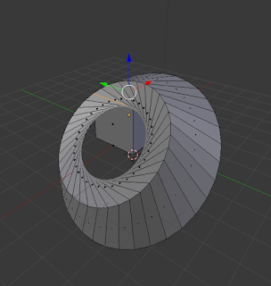
Spin Technique on face

Merge (Alt + M):

This technique merges multiple  vertices, edges, or faces together. It is generally only used on vertices or edges.
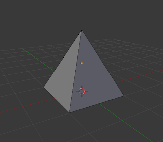
Merge Technique

Subdivide:

Subdivide is used to divide the face of an object into separate segments, thus creating more faces upon the one that has been divided. There is no keyboard shortcut so just use the sub-divide button and options in the toolbar.
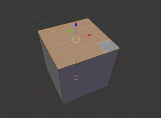
Subdivided Technique

Knife (K):

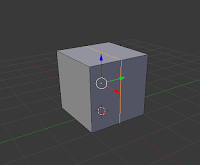
The knife technique allows you to manually cut through vertices and faces, creating new vertices, edges and faces.
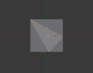
Knife Technique used to cut surface of face

Loop, cut and slide (Ctrl + R): 

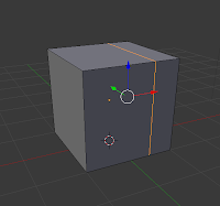
This is a process with three parts, as the name suggests - loop, cut, and slide. The first is to loop a selection around an object, choosing which axis to cut on. The second is cut, which cuts the object on the chosen axis. The final is slide, in which you can slide the cut along the edge or face, before clicking and finishing the cut.
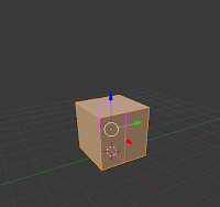

Loop
Cut
Slide

Fill (F):

This allows the user to fill in a gap that may appear in an object in the scene.
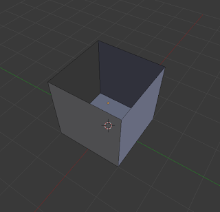
Gap that may appear
Gap is filled in with Fill technique

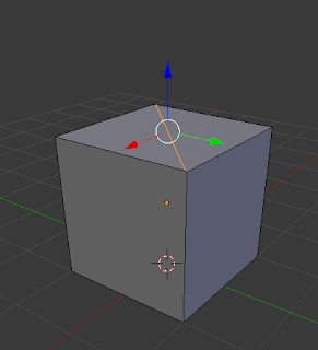
Bisect:

This is used to split objects into separate sections. There is no keyboard shortcut so just use the bisect button and options in the tool bar.
Manual Bisection
Lifted Bisection to show properly

Try some of these techniques yourself. Once you familiarize yourself with them, you can go onto experiment and make a lot of high quality objects and scenes in Blender.

Sample scene created with Polygon Modelling techniques


Wednesday, July 13, 2016

3D Modelling Basics & Terminology3D

3D Modelling Basics
3D Modelling Software Screenshot


This article on 3D modelling is the first of 5 articles on the topic of 3D Graphics and Animation. In this instance, 3D graphics means computer generated three-dimensional graphics. In 3D graphics, elements are visualized by creating three-dimensional models out of them. The final image is rendered from a virtual scene that utilizes several elements which are familiar from real life such as lights, materials and cameras. 3D graphics can be seen in multiple different forms such as an image, an animation or real time visualization inside of a computer game.

The creation of 3D graphics is a complicated process and therefore is, in my opinion, easier to understand when discussed in small pieces, hence the 5 article series. First up it's 3D Modelling which refers to the creation of the 3D model itself.


3D Modelling - The Parts...

A 3D model is a mathematical representation of an object. 3D modelling can be compared to sculpting. Artist builds or moulds a 3D object by taking into account all different sides and angles. 3D models consist of smaller elements (vertex, edge, face, polygon) which can be manipulated individually in whatever software you are using to model your 3D object, such as Blender, Maya or 3D Studio Max.

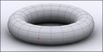
Vertex:

3d modelling vertex
vertex


Vertex is the smallest building block of a 3D model. Vertex is a point where two or more edges meet and where corners of faces or polygons meet. In a 3D model a vertex is shared between all connecting edges, faces and polygons. Transforming a vertex affects all connected edges, faces and polygons.

Edge:

3d modelling edge
edge

Edge is a line between two vertices. Edges are border lines of faces and polygons. In a 3D model an edge is shared between two adjacent faces or polygons. Transforming an edge affects all connected vertices, faces and polygons.

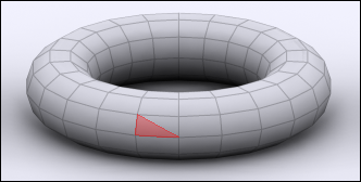
Face:

3d modelling face
face


Face is a triangle. Face is a surface between three corner vertices and three surrounding edges. Transforming a face affects all connected vertices, edges and polygons.

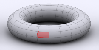
Polygon:

polygon
polygon

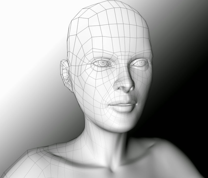
Polygon is an even surface which has four or more corners and is made of two or more faces. A polygon is surrounded by edges and has a vertex in each corner. Animated high quality 3D characters are often made mostly of four-sided polygons. Polygons with 5 or more sides can cause problems in deforming surfaces such as a human face.

3D Modelling - The Techniques...

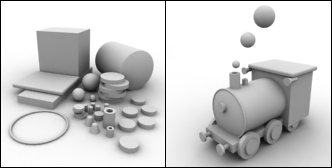
3D models can be created in many different ways. The choice of modelling technique depends on the requirements and the complexity of the object. The following list describes some of popular 3D modelling techniques:

Standard Primitives and Modifiers:

3d modelling Primitives and Modifiers
Primitives and Modifiers

Many 3D software packages include tools for creating standard objects such as boxes and spheres easily. One of the simplest 3D modelling techniques is to combine these standard objects to create complex 3D models. 3D Studio MAX includes standard objects such as sphere, cube and tube. These standard objects can be modified through their parameters (radius, height etc.) or through special modifiers (stretch, bend etc.). By combining several different standard objects and by modifying them, one can create complex 3D models.

Polygon Modelling:

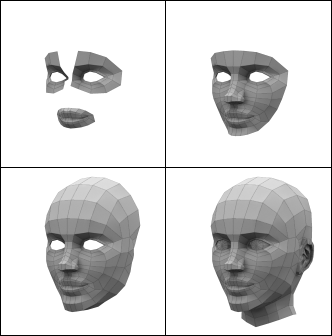
Stages of Polygon Modelling

Complex objects are often modeled polygon by polygon. 3D software packages include many efficient tools for creating and manipulating polygons.
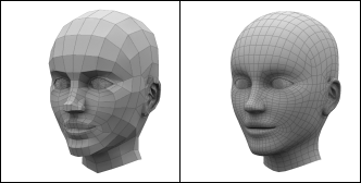
Subdivision surface means a surface which is created by dividing the original 3D model into smaller polygons. At the same time 3D model's corners become rounder and the surface becomes smoother. Subdivision surfaces is a very popular modelling technique. The advantage of a subdivision surface is the fact that one can create a coarse 3D model which is then automatically subdivided into a smoother surface.


3d modelling
A Polygon Model Before and After Subdivision

Boolean Operations:

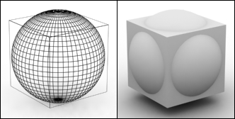
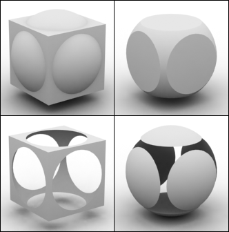
The starting point of Boolean operation is two overlapping 3D objects. Boolean operations are prone to error and the resulting geometry might have underlying problems.


3d boolean modelling
Boolean Modelling

Boolean operation has four possible results:

The 4 Possible Outcomes of a Boolean Operation
The 4 Possible Outcomes of a Boolean Operation 
  • Union: Two 3D models are combined and the unnecessary geometry inside of the Models is removed.
  • Intersection: Overlapping a part of the two 3D objects.
  • Subtraction (A-B): Object A is subtracted from object B.
  • Subtraction (B-A): Object B is subtracted from object A.


NURBS:

NURBS stands for Non-Uniform Rational B-spline. In NURBS modelling, lines and surfaces are not manipulated by moving vertices, edges, faces or polygons. Instead NURBS surfaces and lines are manipulated by special control points. The following 2 techniques make use of NURBS.

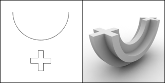
Solid of Revolution:

A cross section and the object created by a solid of revolution

Solid of revolution is made of one line. The line represents a half cross-section of the object. Solid of revolution is created by revolving the line around a specified axis which then creates the form of the object in 3D.

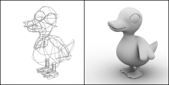
Lines:

A 3D object and the cage of lines used to create it

3D objects can be created by creating a cage of lines which can be then be converted to a solid 3D surface. This can be a difficult technique to master as it can be hard to visualise the outcome of the lines once they are solidified but once mastered it allows for very quick modelling of objects.

Now that you understand the basics of 3D modelling, why not give it a try, it won't cost you a penny either! We recommend the free software Blender to get you started but there are many other great free 3D modellling softwares. The tutorials linked to below are also a good place to learn the basics of modelling 3D objects. 

Or, if you're not ready for that yet, read the next tutorial in the 3D Modelling and Animation series - 3D Lighting techniques.


close
Banner iklan disini